
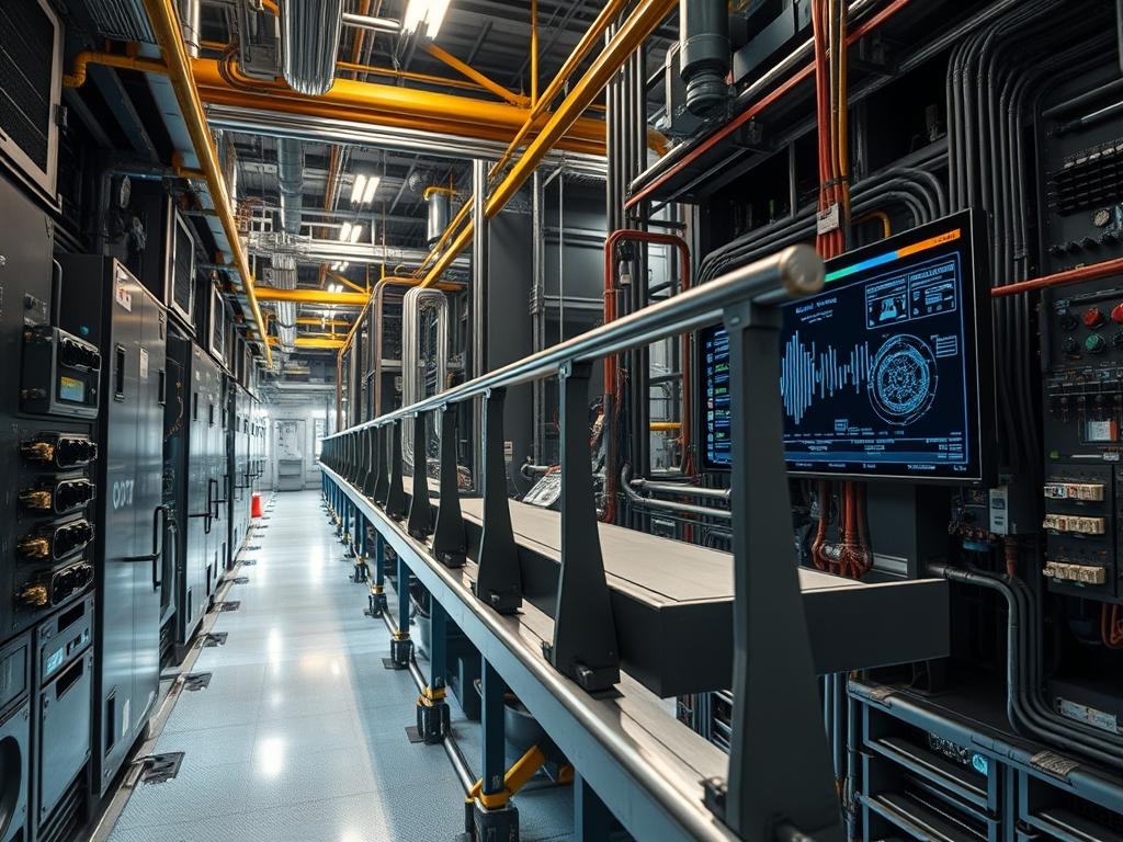
Fall Protection Guardrails function as the primary physical perimeter layer within the solar deployment stack, providing a passive safety boundary that prevents gravitational failure events. Unlike active fall arrest systems like harnesses and lanyards, which require active user-space interaction and tethering, guardrails operate as a daemonized safety service that protects all entities within the work zone without individual configuration. The system purpose is to mitigate the risk of perimeter breach on industrial rooftops by establishing a rigid physical firewall at the roof edge. This integration layer is critical during the installation of photovoltaic arrays, where worker throughput is high and focus is concentrated on string wiring and module placement. Operational dependencies include the structural integrity of the roof deck substrate and the coefficient of friction between base plates and the roof membrane. A failure in the guardrail system represents a total catastrophic outage, as the physical protection layer is the last line of defense before a high-velocity impact event. Resource implications involve the dead load added to the building envelope, requiring structural validation to ensure the assembly does not exceed the pounds-per-square-foot rating of the decking or the thermal insulation beneath the membrane.
Technical Specifications
| Parameter | Value |
| :— | :— |
| System Logic | Passive Physical Boundary |
| Compliance Standard | OSHA 1926.502(b) |
| Vertical Height | 42 inches (+/- 3 inches) |
| Top Rail Displacement | 200 lbs lateral force capacity |
| Mid Rail Displacement | 150 lbs lateral force capacity |
| Toe Board Requirement | 3.5 inches minimum height |
| Material Composition | 1.66 inch OD Galvanized Steel or Aluminum |
| Base Plate Weight | 90 lbs to 110 lbs (weighted systems) |
| Surface Compatibility | TPO, EPDM, Built-up, Metal Deck, Concrete |
| Operating Temperature | -40F to 160F |
| Security Level | Physical Access Control Level 1 |
—
Configuration Protocol
Environment Prerequisites
Prior to deployment, the physical environment must meet specific structural and regulatory prerequisites. Documentation of the roof deck composition is required: whether it is 22-gauge steel, 3000 PSI concrete, or timber. The deployment team must verify that the roof membrane is free of oils or loose particulates that could cause base plate drift, effectively reducing the friction coefficient. Required tools include a calibrated torque wrench, an impact driver with a 3/4-inch socket, and a digital inclinometer to verify rail verticality. Compliance with local building codes and ANSI A1264.1 is mandatory. If the deployment occurs on a pitched roof exceeding a 4:12 ratio, specialized anchoring protocols or non-weighted penetration systems must be utilized to prevent down-slope migration.
Implementation Logic
The engineering rationale for Fall Protection Guardrails centers on the hierarchy of controls. By moving safety from a user-managed process (active fall arrest) to an infrastructure-managed process (passive guardrails), the system eliminates the “human-in-the-loop” failure point. The architecture utilizes a modular design where individual rail segments are encapsulated by upright posts and weighted base plates. This design allows for high concurrency; multiple workers can utilize the perimeter simultaneously without the throughput bottlenecks associated with shared anchor points. The communication flow between components is purely mechanical: lateral force applied to the top rail is transferred via the upright into the base plate, where gravitationally induced friction dissipates the energy into the roof substrate. This encapsulation ensures that a failure in one segment (e.g., a loose set screw) does not necessarily propagate a total system collapse, provided the neighboring sections remain coupled.
—
Step By Step Execution
Phase 1: Substrate Integrity Audit
Verify the structural capacity of the host environment using a UT thickness gauge or visual structural inspection. Identify any soft spots in the insulation or compromised sections of the deck that cannot support the point load of a 100-pound base plate. Mapping the layout must ensure that the perimeter follows the roof edge with no gaps exceeding 19 inches.
System Note: Use a thermal imager to detect moisture trapped under the membrane; wet insulation significantly reduces the load-bearing capacity and increases the risk of the guardrail sinking over time.
Phase 2: Base Plate Distribution and Alignment
Position weighted base plates along the pre-marked perimeter. For non-penetrating systems, the bases must be spaced according to the manufacturer’s logic, typically every 8 to 10 feet. Ensure that the base plate rubber pads are clean and making full contact with the surface to maintain the design friction coefficient.
System Note: On TPO membranes, a slip-sheet or extra layer of membrane should be placed under the base plate to prevent thermal expansion from causing abrasive wear on the primary roof layer.
Phase 3: Upright and Rail Integration
Insert the vertical uprights into the base plate receivers and secure them using the primary locking pins or set screws. Then, slide the horizontal rails through the upright sleeves. The top rail must sit at the 42-inch mark, with the mid-rail positioned exactly halfway between the top rail and the deck.
System Note: Utilize a torque wrench to tighten all set screws to the manufacturer-specified value, typically 30 to 40 foot-pounds, to prevent vibration-induced loosening.
Phase 4: Inter-Segment Coupling and Locking
Secure each rail segment at the junctions. If the system uses telescopic rails, ensure a minimum 6-inch overlap. For fixed-pipe systems, use internal couplings. The end of a rail run must be terminated with a 90-degree return or anchored to a structural wall to provide lateral stability to the entire “string.”
System Note: Check the assembly logic with a Fluke digital level to ensure the uprights are within a 2-degree tolerance of true vertical.
Phase 5: Toe Board Configuration
Install toe boards at the base of the uprights if there is a risk of equipment falling onto lower levels. The toe board must be secured to the uprights with no more than a 0.25-inch gap between the board and the roof surface.
System Note: Ensure the toe board material is UV-rated to prevent brittle failure and subsequent debris shedding in high-solar-radiation environments.
—
Dependency Fault Lines
Deployment failures in Fall Protection Guardrails often stem from environmental mismatches or mechanical degradation. Common issues include:
- Substrate Compression: On roofs with low-density insulation, the heavy base plates can compress the material, creating “divots” that lead to rail instability and potential water pooling.
- Coefficient of Friction Loss: Dust, silt, or ice on the roof membrane acts as a lubricant, allowing the base plates to slide under lateral load. This results in a failure to meet the 200-pound resistance requirement.
- Vibration-Induced Loosening: High-wind environments create micro-vibrations in the rail segments. Over time, this acts as a mechanical “packet loss,” where set screws back out and the coupling between the rail and the upright is severed.
- Galvanic Corrosion: If aluminum rails are used with non-compatible steel fasteners in a high-salt environment, the structural integrity of the joint will degrade (signal attenuation).
Remediation requires scheduled physical audits. If a base plate has migrated more than 2 inches from its original position, the surface must be cleaned and the plate re-indexed. Loose fasteners must be extracted, inspected for thread damage, and re-torqued.
—
Troubleshooting Matrix
| Symptoms | Root Cause | Verification Method | Remediation |
| :— | :— | :— | :— |
| Rail Jitter/Play | Loose set screws or worn couplings | Manual shake test at mid-span | Re-torque fasteners to 35 ft-lbs |
| Surface Scoring | Base plate migration | Visual inspection of membrane | Install slip-sheets under bases |
| Structural Sag | Substrate failure or over-extension | Caliper check of rail deflection | Reduce post spacing; add supports |
| Component Rust | Protective coating breach | Visual: Check for oxidation flakes | Apply cold-galv spray or replace |
| Out-of-Plumb | Uneven roof surface | Inclinometer readout | Leveling shims or adjustable bases |
System Log Example (Manual Audit):
`[2023-10-24 08:30] AUDIT: Node_Perimeter_South: PASS. Torque verified at all 12 points.`
`[2023-10-24 09:15] ALARM: Node_Perimeter_West: FAIL. Base plate drift detected (>3 inches). Surface debris identified as causal factor.`
`[2023-10-24 09:45] EVENT: Remediation initiated. Surface cleaned; hardware re-indexed.`
—
Optimization And Hardening
Performance Optimization
To increase the throughput of the installation team, the guardrail layout should be optimized for logistical flow. Position access gates near the primary material hoisting area to reduce travel distance. Use modular components that allow for hot-swapping segments if a rail is damaged by a forklift or crane during solar module delivery, ensuring the “uptime” of the safety perimeter remains at 100 percent.
Security Hardening
Hardening the system involves preventing unauthorized modification. Use security-head set screws that require specialized bits to prevent tampering. Access gates should be equipped with self-closing hinges and gravity latches to ensure the “firewall” automatically closes after an entity passes through.
Scaling Strategy
For massive utility-scale rooftops, the guardrail system should be treated as a series of load-balanced clusters. Rather than one continuous 2000-foot run, utilize structural breaks or returns every 200 feet. This limits the “blast radius” of a potential mechanical failure, such as a wind-induced harmonic oscillation that could affect a long, non-interrupted line of rails.
—
Admin Desk
How can I verify the system meets the 200-pound load requirement?
Utilize a calibrated tension dynamometer attached to the top rail. Apply 200 pounds of force in an outward and downward direction. The rail should not fail or deflect to a point where it creates a secondary hazard.
What is the maximum allowable gap between rail segments?
The horizontal distance between upright posts should not exceed manufacturer specs, usually 8 to 10 feet. Any gap between the rail ends and a structural wall must be less than 19 inches to prevent an entity from passing through.
How do I handle guardrails on a sloped roof?
For slopes greater than 4:12, use penetrating anchors or a counterweight system designed for high-shear loads. The base plates must be mechanically locked to prevent gravity-induced migration down the roof pitch, which could compromise the perimeter.
Are toe boards always required on solar jobs?
Toe boards are mandatory if there is a risk of tools or modules falling onto personnel below. On most solar sites, where the roof edge is exposed to ground-level traffic or lower-roof tiers, toe boards are a required safety packet.
Can I mix components from different guardrail manufacturers?
Mixing components is forbidden unless explicitly validated by a Professional Engineer. Variations in pipe outer diameter (OD) and wall thickness can cause connection failures, leading to a system-wide collapse under load. Stick to a single-vendor hardware stack.