
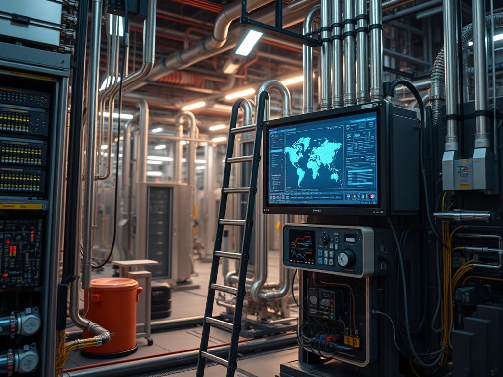
Ladder stabilization hardware functions as the primary physical security layer for vertical access points in critical infrastructure environments: specifically within telecommunications towers, data center galleries, and industrial plant mezzanines. This hardware is designed to eliminate rotational torque and lateral displacement of vertical transit systems during maintenance operations on elevated network gear. By integrating stabilization brackets directly into the structural substrate of a facility, engineers ensure that high-frequency vibration does not propagate through the ladder assembly to sensitive radio frequency or optical equipment. The system serves as a deterministic safety control, moving beyond manual tie-offs to a fixed-node architecture that supports high-load concurrency during emergency hardware swap-outs.
The operational role of this hardware extends to the protection of physical layer integrity. Unstabilized access systems can induce micro-movements in cable raceways: resulting in physical stress on fiber-optic connectors or localized signal attenuation in microwave backhaul alignments. When integrated with Industrial Internet of Things (IIoT) sensors: such as strain gauges and tilt-meters, ladder stabilization hardware contributes real-time telemetry to the facility management system. This data allows for the quantification of structural fatigue and ensures that access points remain within the safety tolerances defined by engineering specifications. The failure impact of poorly secured access points includes catastrophic structural collapse, technician injury, and unplanned service outages caused by kinetic interference with adjacent power or data distribution modules.
Technical Specifications
| Parameter | Value |
| :— | :— |
| Load Rating | 375 lbs (170 kg) per anchor node |
| Material Spec | 6061-T6 Anodized Aluminum / AISI 316 Stainless |
| Fastener Torque | 45 ft-lbs (61 Nm) for M12 Grade 8.8 bolts |
| Sensor Protocol | Modbus RTU / RS-485 or MQTT via ESP32 |
| Operating Temp | -40C to +85C |
| Wind Load Tolerance | Sustained 120 mph (193 km/h) |
| Compliance | ANSI A14.3 / OSHA 1910.23 / EN 131 |
| Telemetry Latency | <100ms (Local gateway polling) |
| MTBF (Sensors) | 150,000 Hours |
| Mounting Surface | Concrete, I-Beam, or Masonry |
—
Configuration Protocol
Environment Prerequisites
Successful implementation requires the verification of the structural mounting surface. For concrete installations, a minimum compressive strength of 3000 psi is mandatory. For steel I-beam attachments, the flange thickness must be validated against the bracket clamp depth. Electronic monitoring requires a shielded Cat6 or RS-485 serial run from the ladder base to a local PLC or gateway. All software-based monitoring relies on Python 3.8+ for the data ingestion daemon and InfluxDB or Prometheus for time-series storage. Root or sudo permissions are required on the gateway to access serial TTY devices or bind to low-level network ports for telemetry export.
Implementation Logic
The engineering rationale for fixed-node stabilization focuses on the mitigation of harmonic resonance. As a technician climbs, the frequency of movement can synchronize with the natural frequency of the ladder assembly. Stabilization hardware increases the stiffness of the system, shifting the resonant frequency outside the range of human movement. From a data perspective, the architecture uses a stateful inspection of sensor inputs. A PID controller logic at the edge processes raw strain data to filter out environmental noise: such as wind gusts: while alerting on sustained structural deflection. This logic ensures that safety alerts are idempotent and based on verified structural anomalies rather than transient vibrations.
—
Step By Step Execution
Physical Anchor Installation
The primary stabilizers must be installed at intervals not exceeding 10 feet. Use a rotary hammer to drill holes if mounting to concrete. For steel, utilize the integrated beam clamps. Ensure the bracket is perpendicular to the ladder rails.
System Note: Verify the verticality using a high-precision laser level. A deviation of more than 0.5 degrees increases the uneven distribution of load across the bolt pattern: potentially leading to shear failure under peak loads.
Sensor Node Integration
Attach the load cell sensors to the center-point of the stabilization brackets. Wire the sensors in a daisy-chain configuration using shielded twisted-pair cable to prevent electromagnetic interference from nearby power lines.
“`bash
Verify the serial connection to the sensor gateway
ls /dev/ttyUSB*
stty -F /dev/ttyUSB0 9600 cs8 -cstopb -parenb
“`
System Note: Use Modbus register mapping to assign a unique ID to each stabilization point. This allows the monitoring service to pinpoint the exact location of a structural fault.
Telemetry Daemon Deployment
Create a service to monitor the load and tilt data. This daemonized service will poll the sensors and write the data to a local log and a remote time-series database.
“`yaml
ladder_monitor.service at /etc/systemd/system/
[Unit]
Description=Ladder Stabilization Monitoring Daemon
After=network.target
[Service]
ExecStart=/usr/bin/python3 /opt/safety/monitor.py –port /dev/ttyUSB0
Restart=always
User=telemetry_user
Group=dialout
[Install]
WantedBy=multi-user.target
“`
System Note: Reload the system manager and start the service to begin log generation.
“`bash
sudo systemctl daemon-reload
sudo systemctl enable ladder_monitor.service
sudo systemctl start ladder_monitor.service
“`
Validation and Load Testing
Apply a controlled static load to the ladder while monitoring the journalctl output. Observe the sensor response to ensure the delta in strain correlates with the applied mass.
“`bash
journalctl -u ladder_monitor.service -f
“`
System Note: Use a Fluke multimeter to check the voltage drop across the sensor loop. A drop of more than 1V indicates high resistance in the wiring which will cause signal attenuation and false negatives in the monitoring software.
—
Dependency Fault Lines
The most common failure in ladder stabilization systems is the loosening of fasteners due to thermal inertia and cyclic loading. In environments with significant temperature swings, the coefficient of expansion for aluminum versus steel leads to torque loss. This produces a “clanking” sound during use and results in increased vibration throughput.
Signal attenuation in the telemetry layer often occurs due to improper shielding. If the RS-485 cable runs parallel to high-voltage AC lines without 12 inches of separation, inductive coupling creates packet loss. This manifests as CRC errors in the monitoring logs.
Kernel module conflicts can occur on the gateway if multiple serial-to-USB converters are used. The cp210x or ch341 drivers may conflict if the device rules are not explicitly defined in udev. This results in the gateway losing connection to the sensor array after a reboot.
—
Troubleshooting Matrix
| Symptoms | Root Cause | Verification Method | Remediation |
| :— | :— | :— | :— |
| `Modbus Error: CRC check failed` | Signal Noise | Check dmesg for EMI spikes | Replace cable with shielded STP |
| `Exit status 1` in systemctl | Permission Denied | `groups telemetry_user` | Add user to dialout group |
| Excessive lateral sway | Loose Brackets | Physical torque test | Re-torque to 45 ft-lbs |
| Sensor data stuck at max | Load cell saturation | Check raw voltage at sensor | Recalibrate or replace sensor |
| Log entry: `STRUCTURAL_ALARM_01` | Angle > 0.5 deg | `tail -f /var/log/syslog` | Inspect anchors for wall pull-out |
—
Optimization And Hardening
Performance Optimization
To reduce latency in safety-critical environments, optimize the sensor polling loop. Use a binary protocol like MQTT with a high Quality of Service (QoS 2) to ensure message delivery. Tune the polling frequency based on activity: increase the rate to 10ms when a “Technician Present” switch is triggered at the base of the ladder, and decrease it to 1000ms during idle hours to conserve gateway resources.
Security Hardening
Isolate the telemetry network from the primary data plane. Use a dedicated VLAN for all stabilization hardware traffic. Implement iptables rules on the gateway to drop any traffic not originating from the authorized monitoring server.
“`bash
Restrict access to the Modbus gateway
iptables -A INPUT -p tcp -s 10.0.5.1 –dport 502 -j ACCEPT
iptables -A INPUT -p tcp –dport 502 -j DROP
“`
Ensure all serial communication is physically protected within RMC (Rigid Metal Conduit) to prevent tampering or physical signal interception.
Scaling Strategy
For sites with more than 50 access points, move from a single gateway to a distributed edge computing model. Each zone should have a local controller that aggregates data before sending it to the central site manager. This creates a failover mechanism where localized stabilization alerts can still trigger audible alarms even if the primary backhaul is down.
—
Admin Desk
How do I verify the hardware is securely anchored?
Perform a torque verification on all fasteners using a calibrated torque wrench. Check for any hairline fractures in the concrete or de-lamination of the mounting substrate. Ensure the brackets do not exhibit any visible movement when a lateral force of 200 lbs is applied.
What causes sensor drift in the monitoring software?
Thermal expansion is the most frequent cause. If the sensors are exposed to direct sunlight, the heat increases the resistance in the strain gauge. Utilize software-based temperature compensation to adjust the baseline based on the ambient thermal reading from the onboard thermistor.
How do I handle a “Serial Port Busy” error on the gateway?
This error typically occurs if a previous instance of the monitoring daemon failed to release the file descriptor. Use fuser -k /dev/ttyUSB0 to identify and terminate the process holding the port, then restart the systemctl service to restore connectivity.
Can these stabilizers be used on temporary scaffolding?
No, ladder stabilization hardware refers to permanent or semi-permanent structural attachments. Temporary setups require different ballast and tie-off protocols. This hardware depends on the rigid structural integrity of a building or tower frame to provide its specified safety and stabilization benefits.
What is the recommended maintenance schedule?
Conduct a physical inspection and data audit every six months. Verify the integrity of the weather-proofing on the sensor junction boxes. Run a script to check for any gaps in the time-series data which could indicate intermittent power or connectivity issues.