
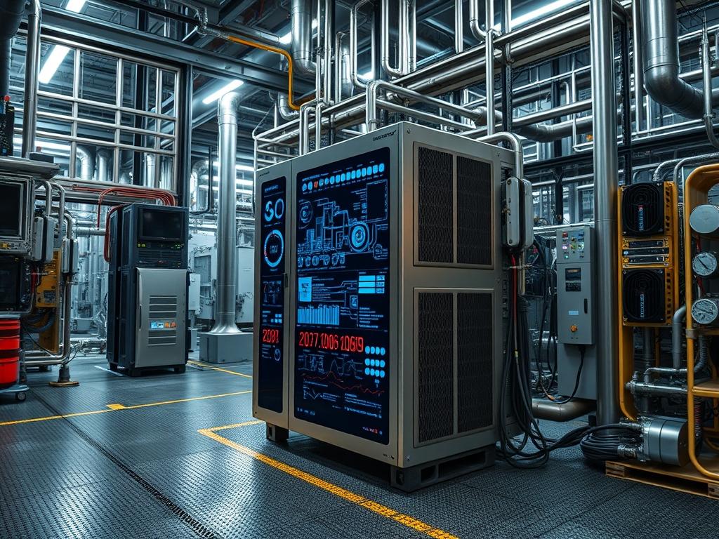
Inverter surge capacity defines the thermal and magnetic ceiling of the power conversion stage during localized transient events. In critical infrastructure, specifically within water treatment, HVAC, and industrial automation, this parameter dictates the system ability to satisfy the high inrush current required by inductive motor loads. Inductive loads, characterized by their magnetic core and copper windings, exhibit high Locked Rotor Amps (LRA) that typically reach 500 percent to 700 percent of their rated full-load amperage (FLA) for durations ranging from 50 to 500 milliseconds. If the inverter surge capacity is insufficient, the DC bus voltage collapses or the power transistors exceed their Safe Operating Area (SOA), triggering protective shutdowns. The integration of high-surge inverters into power distribution networks bridges the gap between stored DC energy in battery banks and the dynamic requirements of AC prime movers. Operational success depends on the alignment of the inverter overload curve with the motor startup curve. Failure to match these characteristics leads to repetitive Under Voltage Lock Out (UVLO) events, thermal fatigue in the MOSFET or IGBT switching stages, and interrupted downstream processes.
| Parameter | Value |
|———–|——-|
| Surge Ratio | 2.0:1 to 3.0:1 of nominal RMS rating |
| Maximum Surge Duration | 100ms to 10 seconds (at 200% load) |
| Output Waveform | Pure Sine Wave (THD < 3%) |
| Nominal System Voltages | 12V, 24V, 48V, or 400V DC |
| Communication Protocols | Modbus RTU, CANbus, SNMP |
| Operating Temperature | -20C to +50C (De-rating above 40C) |
| Switching Frequency | 10 kHz to 20 kHz (IGBT/MOSFET) |
| Fault Tolerance | Short circuit, Overload, Over-temperature |
| Typical Cooling | Active forced-air with variable-speed PWM fans |
| Response Latency | < 20 microseconds for peak current limiting |
Environment Prerequisites
Implementation requires a verified electrical baseline. The power distribution unit (PDU) must comply with National Electrical Code (NEC) Article 430 requirements for motor controllers. Upstream DC cabling must be sized not for the continuous load, but for the peak surge current to prevent excessive voltage drop during the startup transient. A maximal 3 percent voltage drop is recommended at peak surge. Batteries must utilize a chemistry, such as Lithium Iron Phosphate (LiFePO4) or high-rate Absorption Glass Mat (AGM), capable of discharging at the inverter peak input current. Any Battery Management System (BMS) in the circuit must have its over-current protection (OCP) threshold set above the inverter maximum DC intake during a surge event. Firmware versions for the inverter and any associated system controllers must be synchronized to ensure high-speed telemetry over the Modbus or CANbus interface.
Implementation Logic
The architecture centers on the energy buffer capacity of the DC link capacitors and the thermal inertia of the output power transistors. When a motor engages, the initial lack of back-electromotive force (Back-EMF) creates a near short-circuit condition. The inverter must transition from its standard PWM (Pulse Width Modulation) logic to a current-limiting or “hard-surge” mode. During this phase, the controller monitors the di/dt (rate of current change) to distinguish between a legitimate motor start and a true short circuit. Thermal management logic monitors the junction temperature of the IGBT or MOSFET stack. If the calculated I2t value (current squared multiplied by time) exceeds the semiconductor thermal dissipation capacity, the system initiates a controlled shutdown to prevent catastrophic failure of the silicon wafers.
Step By Step Execution
Analyze Motor LRA and RLA Data
Inspect the physical nameplate of the motor to identify the Locked Rotor Amps (LRA) and Rated Load Amps (RLA). If specific LRA data is missing, utilize a Fluke 376 FC clamp meter with “inrush” mode activated to capture the peak current during a live start under load. This measurement provides the baseline for sizing the inverter Peak Output Current.
System Note: Ensure the measurement is taken at the mechanical load maximum to account for friction and inertia, which extend the duration of the inrush period.
Configure Inverter Current Limiters
Access the inverter controller via the RS485 port using a laptop and a serial-to-USB adapter. Use a terminal emulator or the manufacturer provided software to adjust the Current Limit register. For an inductive load, set the limit to at least 150 percent of the motor LRA if the hardware allows.
“`bash
Example Modbus RTU command to set surge limit (Hypothetical Register 40102)
modbus_client -m rtu /dev/ttyUSB0 -a 0x01 -r 40102 -w 0x0258
“`
System Note: Register 40102 often controls the peak amperage duration. Setting this to 0x0258 might represent a 600ms window before the OCP triggers.
Align Battery BMS Discharge Parameters
Log into the BMS interface over CANbus or Bluetooth. Verify that the Peak Discharge Current setting exceeds the DC-side equivalent of the AC surge current. Calculate this as (Inverter Peak AC Watts / Inverter Efficiency / Minimum Battery Voltage). If the BMS shuts down at 200A but the inverter pulls 250A during a motor start, the system will fail regardless of inverter capacity.
System Note: Use a Victron SmartShunt or similar high-precision shunt to monitor real-time DC current during the commissioning phase.
Implementation of Soft-Start Logic
If the inverter supports frequency scaling, configure the V/f curve (Voltage to Frequency ratio). By reducing both voltage and frequency during the first 2 up to 5 seconds of the motor ramp-up, you reduce the LRA requirement. This is typically managed via an internal PID controller or a dedicated Soft-Start profile in the inverter firmware.
“`yaml
Example Configuration Snippet for Inverter Control Gateway
motor_control_profile:
start_type: “v_f_ramp”
start_frequency_hz: 10
target_frequency_hz: 60
ramp_time_seconds: 3.5
surge_threshold_amps: 45
“`
System Note: Soft-starting through the inverter reduces mechanical stress on the motor couplings and minimizes the thermal load on the inverter switching bridge.
Dependency Fault Lines
A common failure point is the DC bus impedance. High resistance at the battery terminals or improperly crimped lugs causes a significant voltage dip at the inverter input. When the input voltage falls below the UVLO threshold, the inverter ceases switching, even if it has the internal capacity to handle the surge. This is a “phantom” surge failure where the inverter is blamed for a battery or cabling bottleneck.
Another fault line is the power factor (PF) of the motor. Inductive motors often have a startup PF as low as 0.3. This lagging current means the inverter must handle significantly more reactive power (VARs) than real power (Watts). Inverters rated only for resistive loads (PF 1.0) will fail when attempting to drive these loads due to the phase shift between voltage and current causing premature saturation of the output transformer.
Port collisions or data lag on the Modbus network can also lead to failure. If a system controller is polling the inverter for data too frequently during a surge event, the internal CPU may prioritize communication interrupts over the high-speed current-tracking loop, leading to a delayed OCP trip or hardware damage.
Troubleshooting Matrix
| Symptom | Fault Code | Tool | Resolution |
|———|————|——|————|
| Instant shutdown upon motor start | E01 (Overcurrent) | Oscilloscope | Increase current limit or install soft-starter. |
| Inverter reboots during surge | E03 (Undervoltage) | Multimeter | Check DC cable gauge and battery SOC. |
| Motor hums but does not rotate | E07 (Low Freq) | Tachometer | Verify V/f settings; motor is under-torqued. |
| High-pitched whine from inverter | N/A | Thermal Camera | Inspect transformer core for magnetic saturation. |
| Communication loss under load | TIMEOUT | Wireshark | Replace unshielded RS485 with shielded twisted pair. |
Monitor the system logs using journalctl on the management gateway:
`journalctl -u power-daemon -f`
Look for entries such as “DC_VOLTAGE_SAG_DETECTED” or “AC_OUTPUT_CLIPPING”. Use snmptrapd to catch asynchronous alerts from the inverter during the 500ms surge window.
Optimization and Hardening
Performance Optimization
To maximize throughput and minimize latency during transients, adjust the switching frequency. Lowering the switching frequency from 20 kHz to 10 kHz reduces switching losses and allows the components to run cooler during sustained surges. Enhance thermal efficiency by implementing an external fan trigger based on the Modbus temperature register before the motor actually starts.
Security Hardening
Isolate the power management network from the primary enterprise network using a VLAN. Implement IPtables on the gateway to allow only specific IP addresses to write to the inverter configuration registers. Use read-only community strings for SNMP monitoring to prevent unauthorized changes to the surge duration settings.
Scaling Strategy
For high-demand environments, utilize parallel-redundant (N+1) inverter configurations. Use a Master-Slave architecture over a high-speed CANbus to ensure all inverters are phase-synchronized. When a surge is detected, the load is distributed across the entire parallel stack, effectively doubling or tripling the surge capacity.
Admin Desk
How do I calculate the minimum inverter size for a 2HP pump?
A 2HP motor typically pulls 12A RLA at 230V. Startup LRA is approximately 60A. Ensure the inverter surge capacity is rated for at least 72A (RLA + 500 percent) for a minimum of 1 second to ensure rotor breakaway.
Why does my inverter trip even though the motor RLA is low?
The trip is likely caused by the peak LRA, not the RLA. High-inertia loads like fans or loaded compressors maintain LRA for longer periods. Check the inverter I2t curve versus the motor acceleration time to find the mismatch.
Can I use a resistive-rated inverter for a motor load?
No. Resistive-rated inverters assume a Power Factor of 1.0. Inductive loads introduce reactive current that can saturate the inverter output stage. Always specify an inverter with high surge capacity and a 0.8 to 1.0 PF support range.
What is the impact of long AC cable runs on surge?
Long AC cables increase impedance, which can actually limit the inrush current but can also cause a voltage drop at the motor. This leads to longer start times and increased thermal stress. Keep AC runs as short as possible.
How often should I inspect the surge-protection components?
Perform a thermal scan of the DC busbars and AC output terminals every six months. Check for loose connections, as high-current vibration during repetitive surges can loosen mechanical fasteners, leading to resistive heating and eventual terminal failure.