
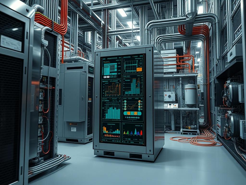
Electrical Subpanel Supports function as the primary structural interface between heavy localized power distribution enclosures and the building substrate. Within high density data centers, industrial automation nodes, or edge computing facilities, these supports ensure the mechanical stability of the power distribution chain. The problem-solution relationship centers on mitigating structural deflection and vibration induced by high amperage magnetic fields, which can lead to termination fatigue if not properly constrained. These brackets act as the integration layer between the facility architectural shell and the electrical distribution system, supporting the transition from primary trunk lines to branch circuits. Operational dependencies include structural load bearing capacity, seismic bracing compliance, and effective thermal clearance for heat dissipation from the subpanel chassis. Failure of these supports results in mechanical stress on busbars and feeder cables, potentially leading to arcing, localized hotspots, or total system blackout. By maintaining precise vertical and horizontal alignment, custom brackets optimize the enclosure footprint and ensure that the ingress of conduits aligns perfectly with pre-punched knockouts, reducing the risk of cabinet deformation under the weight of oversized copper conductors.
| Parameter | Value |
| :— | :— |
| Material Specification | AISI 304 Stainless Steel or A36 Structural Carbon Steel |
| Minimum Material Thickness | 3.175mm (11 Gauge) for support members |
| Operating Temperature Range | -40C to +85C |
| Loading Factor Safety Margin | 400 percent of static load |
| Seismic Design Category | C, D, or E based on ASCE 7-22 |
| Industry Standards | NEC Article 312, NEMA PB1, UL 67 |
| Default Fastener Torque | 30 to 45 foot-pounds (Grade 5 bolts) |
| Grounding Interface | Exothermic weld or UL-listed mechanical lug |
| Corrosion Resistance | Hot-dip galvanized per ASTM A123 |
| Environmental Tolerance | Salt spray resistance up to 500 hours (Class 1) |
Environment Prerequisites
Installation requires verified architectural drawings indicating the location of structural steel members or reinforced concrete walls. Personnel must possess valid OSHA 10 safety certification and be proficient in the use of a Fluke 1732 Three-Phase Power Logger for pre-installation load studies. The assembly environment must be free of combustible dust if welding is required. Necessary tools include a DeWalt magnetic drill press, Hilti HIT-RE 500 V3 epoxy anchors for concrete, and a calibrated Proto torque wrench. Structural calculations must be validated by a Professional Engineer (PE) to ensure the building substrate can handle the concentrated point loads of the Electrical Subpanel Supports.
Implementation Logic
The engineering rationale for custom brackets rests on the need for idempotent positioning of subpanels in non-standard spaces. Standard off-the-shelf supports often fail to account for the thermal expansion of high-capacity feeders or the specific vibration profiles of nearby industrial machinery. The architecture utilizes a cantilevered or bridge-mount design to isolate the panel from the primary wall surface, creating a thermal chimney effect that assists in cooling the enclosure. This design handles the dependency chain where the electrical conduit provides the payload, the subpanel provides the interface, and the bracket provides the structural integrity. By delegating the mechanical load to the bracket rather than the conduit connectors, we prevent shear stress on the cabinet wall. Failure domains are compartmentalized; if a single bracket member fails, the redundant cross-bracing maintains the panel in a safe state until remediation can occur.
Substrate Mapping and Anchor Point Preparation
Locate the vertical and horizontal centerlines of the intended installation site using a laser level. Mark the anchor points according to the CAD-generated bracket template. If mounting to concrete, drill holes using a carbide-tipped bit to a depth of at least 4 inches.
System Note
Use a vacuum-shrouded drill to prevent dust ingress into existing electrical equipment. The use of HEPA filtration during this phase protects nearby server air intakes from particulate contamination. Clean the holes with compressed air to ensure the Hilti epoxy achieves maximum bonding strength.
Bracket Fabrication and Surface Preparation
Cut the structural steel sections to length using a horizontal band saw to ensure square ends. Drill the mounting holes 1/16th of an inch larger than the fastener diameter to allow for minor thermal expansion. Deburr all edges to prevent damage to electrical conductors during the wire pulling phase.
System Note
After fabrication, the bracket must be treated with a zinc-rich primer or hot-dip galvanization. This prevents the formation of an electrolytic cell between the steel bracket and the aluminum or steel subpanel enclosure, which would lead to galvanic corrosion over a multi-year service life.
Primary Bracket Installation
Secure the main vertical support members to the wall using the prepared anchors. Tighten the fasteners to 50 percent of the target torque to allow for final alignment adjustments. Verify the plumb and level status using a precision digital inclinometer.
System Note
Inspect the anchor embedment depth using a depth gauge. In seismic zones, ensure that the bracket includes diagonal bracing (K-bracing) to counteract lateral forces. This structural hardening is critical for maintaining idempotent alignment during a seismic event.
Subpanel Mounting and Torque Verification
Lift the subpanel onto the bracket assembly using a mechanical lift or two-person team. Align the chassis mounting holes with the bracket slots. Insert Grade 5 or Grade 8 bolts with flat washers and split-lock washers.
System Note
Apply Loctite 242 threadlocker to the bolts before final tightening. Use the Proto torque wrench to reach the specified 40 foot-pounds. Over-tightening can lead to stress fractures in the bracket, while under-tightening allows for micro-vibrations that can loosen the assembly over time.
Grounding and Bonding Integration
Install a copper bonding jumper between the subpanel enclosure and the custom bracket. Ensure the contact surface is stripped to bare metal and coated with an antioxidant compound like Burndy Penetrox A.
System Note
Test the resistance of the bonding connection using a Megger low-resistance ohmmeter. The reading must be below 0.1 ohms to satisfy NEC requirements. This ensures the bracket is part of the Effective Ground-Fault Current Path (EGFCP), triggering the upstream overcurrent protection device during a fault.
Dependency Fault Lines
Deployment failures often stem from material fatigue or fastener loosening due to resonance. If the subpanel is mounted near large motors or HVAC compressors, the bracket may enter a state of resonance, leading to cyclic loading and eventual cracking of the welds. The root cause is a failure to calculate the natural frequency of the bracket assembly. Remediation involves adding stiffeners or dampening pads to shift the resonance frequency away from the source vibration.
Another common fault line is galvanic corrosion between dissimilar metals. If a stainless steel bracket is bolted directly to a galvanized steel subpanel without a dielectric washer or proper coating, moisture in the air will facilitate ion transfer, weakening the bracket. Verification involves visual inspection for white or red rust at the contact points. Remediation requires the installation of nylon spacers or the application of heavy-duty cold-galvanizing spray to isolate the materials.
Thermal bottlenecks can occur if the bracket design blocks the enclosure vents. The observable symptom is an unexpected rise in internal temperature during peak load. Verification is performed using a FLIR thermal camera to map heat maps across the panel face. If the bracket restricts airflow, it must be modified with additional standoffs to restore the required 2-inch clearance.
Troubleshooting Matrix
| Symptom | Fault Code / Log Entry | Verification Method | Remediation |
| :— | :— | :— | :— |
| Discoloration at boltheads | N/A (Visual) | Thermal imaging (FLIR) | Re-torque fasteners; check for unbalanced loads |
| Hum or Rattle | 60Hz audible resonance | Vibration analysis via accelerometer | Install rubber isolation mounts |
| High Ground Resistance | > 0.1 Ohms on Megger | Continuity test to main bus | Clean contact points; apply Penetrox |
| Bracket Deflection | > 2mm from vertical | Plumb bob or laser level check | Replace with higher gauge steel |
| Anchor Pull-out | Concrete cracking | Visual inspection of anchor head | Re-drill and use chemical anchors |
When reviewing logs, look for SNMP traps from the subpanel monitoring system indicating “Internal Ambient Temp Over Limit.” This often points to a structural blockage of the cooling path caused by the support bracket. Cross-reference this with a physical inspection of the bracket orientation.
Performance Optimization
To optimize the throughput of air around the subpanel, the bracket should utilize a minimalist skeleton frame rather than a solid plate design. This reduces thermal inertia and prevents the bracket from acting as a heat sink that retains warmth near the enclosure. Capacity planning should include a 25 percent overhead for future subpanel upgrades, allowing heavier enclosures to be mounted on the same support structure without requiring new wall penetrations.
Security Hardening
Physical security is addressed by using tamper-resistant fasteners (such as Torx with pin) for the bracket-to-panel interface. This prevents unauthorized removal or displacement of the subpanel. The bracket design should also incorporate a shroud or lockable cover for the main mounting bolts to prevent sabotage. Service isolation is maintained by ensuring the bracket does not cross-contaminate different voltage zones; separate brackets should be used for high-voltage and low-voltage enclosures to maintain clear air space.
Scaling Strategy
For horizontal scaling in large facilities, a modular unistrut-based bracket system is recommended. This allows for a repeatable implementation logic where the same engineering drawings can be applied to different panel sizes. Redundancy design involves using a dual-rail support system where each rail is capable of supporting the full weight of the panel independently. This provides a failover mechanism if one side of the support structure is compromised during an industrial accident.
Admin Desk
How is the maximum load for a custom bracket determined?
Calculations must account for the subpanel weight, the weight of all internal breakers, and the tensile load of the heavy-gauge conductors. Apply a safety factor of four to the total static weight to accommodate dynamic forces during cable installation.
When should I use stainless steel over galvanized carbon steel?
Use AISI 304 or 316 stainless steel in environments with high humidity, chemical exposure, or salt air. Galvanized steel is sufficient for climate-controlled indoor data centers where the risk of oxidative stress is significantly lower.
What is the correct procedure for a failed anchor?
Do not re-use the same hole. Shift the bracket up or down by at least three times the anchor diameter. Fill the old hole with high-strength structural grout to maintain the integrity of the building substrate.
Does the bracket require its own dedicated grounding wire?
Yes, per NEC 250.4, all non-current-carrying metal parts likely to become energized must be bonded. Use a minimum 6 AWG copper wire to connect the bracket to the equipment grounding conductor of the subpanel.
How often should torque values be audited on these supports?
Perform a manual torque check six months after the initial installation to account for material settling. Subsequently, include a visual inspection and a 10 percent sample torque test during the annual preventative maintenance cycle.