
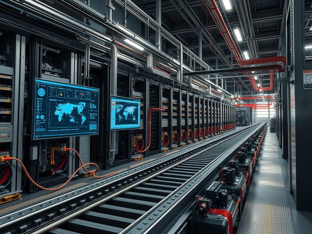
Racking Rail Alignment defines the structural precision required to maintain the physical integrity and thermal efficiency of high-density compute environments. In the context of EIA-310-D and IEC 60297-3-100 standards, the alignment of vertical and horizontal mounting members determines the mechanical stress exerted on server chassis and the deterministic behavior of airflow within the cold aisle. Misalignment of even 2 millimeters can induce board flex in 1U or 2U nodes, leading to intermittent memory DIMM seating issues or high-speed backplane signal degradation.
The problem-solution relationship centers on the elimination of cumulative vertical tilt and horizontal skew. Proper alignment ensures that sliding rail assemblies operate without binding, which prevents the mechanical stalling of hardware during hot-swap maintenance. This physical layer integrates directly with the data center cooling strategy: uniform rail positioning allows for the airtight installation of blanking panels, preventing the recirculation of exhaust air. Operational dependencies include floor load-bearing capacity and the squareness of the base frame. Failure to achieve perfect alignment results in increased thermal inertia, localized hotspots, and potential structural resonance during high-frequency vibration events, such as a mass drive-head seek in dense storage arrays.
| Parameter | Value |
| :— | :— |
| Standards Compliance | EIA-310-E, IEC 60297-3-100, RoHS |
| Vertical Rack Unit (U) Height | 1.75 inches (44.45 mm) |
| Vertical Hole Spacing | 0.625, 0.625, 0.5 inch pattern |
| Horizontal Mounting Width | 19 inches (482.6 mm) |
| Alignment Tolerance | +/- 0.02 inches per 10U section |
| Recommended Torque | 25 to 30 inch-pounds for M6 hardware |
| Load Rating (Static) | 2,500 lbs to 4,000 lbs depending on gauge |
| Temperature Range | -40C to 110C (Material expansion threshold) |
| Grounding Standard | TIA-942 / TIA-607-B |
| Material Specification | 12-gauge or 14-gauge cold-rolled steel |
Environment Prerequisites
Successful Racking Rail Alignment requires a NIST-calibrated laser level, a digital inclinometer with 0.1-degree resolution, and a calibrated torque wrench. The physical site must meet NEMA 12 or better for floor levelness. Ensure that the rack frame is unpopulated and that all transit bolts have been removed. Verify that the M6 or 10-32 cage nuts are free of coating defects and that the grounding busbar is accessible for bonding after the rails are secured.
Implementation Logic
The engineering rationale for this protocol follows a datum-first methodology. By establishing a fixed reference point at the bottom-front-left corner of the enclosure, all subsequent measurements are decoupled from floor irregularities. The vertical rails are treated as independent vectors that must remain parallel to the gravity vector and perpendicular to the horizontal frame members. This eliminates the “parallelogram effect” where the rack frame appears square but is skewed internally. The logic assumes that if the front rails are perfectly plumb and the internal depth markers are synchronized, the sliding rail kits for compute nodes will maintain a 90-degree angle to the backplane, protecting high-density copper or fiber interconnects from shear forces.
Establishing the Master Datum Point
Position a laser level at the base of the rack’s front profile to project a vertical line that bisects the mounting holes of the front-left rail. This line serves as the zero-point for all horizontal depth measurements. Align the center of the first U at the bottom of the rack with this laser line to ensure the vertical start-point is uniform across all four posts.
System Note: Use a Fluke or Bosch 3-plane laser level to verify that the vertical rail does not twist (torsion) along its height. Any deviation > 1mm over 42U requires the loosening of the base shoulder bolts and re-shimming the frame feet.
Synchronizing Horizontal Depth Rails
Apply the depth-matching logic by measuring the distance between the front and rear vertical rails at the 1U, 21U, and 42U positions. The measurement must be identical to within 0.5mm. Adjust the rear rail brackets until the horizontal distance is consistent, then apply a temporary hand-tightened hold.
System Note: Verify the depth using a digital caliper. If the distance at 42U is wider than at 1U, the rack will experience “crowding” when installing full-depth chassis, leading to increased friction on the ball-bearing slides and premature wear.
Squaring the Frame and Torquing Hardware
Utilize an inclinometer to measure the angle between the vertical rail and the bottom horizontal brace. It must read exactly 90.0 degrees. Once the frame is square, tighten all M6 bolts to 28 inch-pounds using a star pattern to distribute the tension evenly across the frame.
System Note: Over-torquing can lead to metal fatigue or stripping of the cage nut threads. Use a Snap-on or Tekton torque wrench to ensure the tension is within the elastic limit of the cold-rolled steel.
Final Validation with Physical Dummy Load
Slide a 2U dummy chassis or a weighted shelf into the 20U position (the rack’s approximate center of mass). Observe the movement. The chassis should glide without resistance. If there is a catching sensation, the rails are likely “pinched” (too close together at the rear) or “toed-out.”
System Note: Monitor the IPMI or SNMP thermal sensors of the first live node installed. If one side of the chassis reports a 10% higher temperature than the other, check for air gaps caused by rail misalignment that allow hot air bypass.
Dependency Fault Lines
Floor Pitch and Subsidence:
Root Cause: Variations in concrete slab thickness or settling under load.
Symptoms: The rack leans forward, causing doors to swing open or slide rails to drift.
Verification: Use a spirit level on the top horizontal frame member.
Remediation: Adjust the leveling feet and lock the jam nuts to prevent vibration-induced loosening.
Cage Nut Deformation:
Root Cause: Use of non-standard or low-grade fasteners.
Symptoms: Hardware spins freely or cross-threads during installation.
Verification: Visual inspection of the nut’s spring-steel housing.
Remediation: Replace all fasteners with zinc-plated M6 hardware rated for the specific rail gauge.
Thermal Expansion Differential:
Root Cause: High-density nodes (30kW+ per rack) causing the metal rails to expand at different rates than the outer frame.
Symptoms: Rails that were aligned during setup become jammed when the rack is under full thermal load.
Verification: Measure rail-to-rail width while the equipment is at peak operating temperature.
Remediation: Increase cold-aisle pressure to lower ambient rail temperature or utilize rails with thermal expansion slots.
Troubleshooting Matrix
| Symptom | Verification Method | Root Cause | Remediation |
| :— | :— | :— | :— |
| Slide rail binding | Caliper measurement at front vs. rear | Horizontal skew (Toeing) | Re-align rear rails to match front width |
| Chassis “droop” | Inclinometer on the chassis ear | Loose mounting bolts or thin gauge steel | Install support trays or replace with 12-gauge rails |
| Airflow Bypass | Thermal Camera (FLIR) or smoke pen | Misaligned blanking panels | Re-square vertical rails to eliminate gaps |
| Vibration Alarms | SNMP trap from accelerometer | Mechanical resonance from loose rails | Torque all frame hardware to 30 inch-pounds |
| Door latch failure | Visual gap analysis | Structural frame twist | Re-shim the leveling feet until the frame is plumb |
Log Analysis Example:
If the system logs show repeated IPMI “Chassis Intrusion” or “Physical Security” alerts despite the door being shut, the sensor alignment is likely compromised by a twisted frame.
`journalctl -u ipmid | grep “Chassis”`
Output: `Sensor 0x05: Transition to Critical from Less Severe`
This confirms that the frame has shifted, moving the sensor out of the contact range.
Optimization and Hardening
Performance Optimization through Airflow Control:
Perfect alignment allows for the use of high-efficiency rubber or brush gaskets between the rail and the side panels. This maximizes Static Pressure in the cold aisle, ensuring that the throughput of the server fans is not wasted on internal turbulence. Ensure that no holes remain unoccupied: if a rail is perfectly aligned, blanking panels will snap into place with zero clearance, creating a pressure-tight seal.
Security Hardening via Physical Integrity:
Secure the rails using Pin-in-Torx or other security fasteners to prevent unauthorized removal of entire equipment blocks. In high-seismic zones, harden the alignment by installing seismic bracing (K-braces) that bonds the vertical rails to the building’s structural steel. This reduces the risk of alignment shift during a seismic event, which could otherwise shear power cables or fiber trunking.
Scaling Strategy:
When expanding to a multi-rack row, use baying kits to lock adjacent racks together. The alignment of the first rack in the row (the “Anchor Rack”) dictates the alignment of all subsequent units. Utilize a continuous laser line across the entire row to ensure that the “U” markings are synchronized globally, which simplifies the deployment of row-based networking and busway power distribution.
Admin Desk
How do I fix a rack that is “leaking” air behind the rails?
Verify that the vertical rails are square. If they are canted, blanking panels will not seal correctly. Use high-density foam gaskets between the rail and the side panel. This prevents exhaust air from infiltrating the intake.
What is the tolerance for rail-to-rail width?
The standard width is 17.75 inches between the inner edges of the rails for a 19-inch rack. Tolerance should be +/- 0.01 inches. Deviations beyond this cause slide kits to bind or fail to latch.
Should I align rails before or after power cabling?
Always align before cabling. The weight of heavy power whips and fiber bundles can induce frame twist, making it impossible to square the rails once the cable management system is under tension.
How do I detect rail misalignment using software?
Monitor chassis fan speeds via IPMI. If fans in the same rack position across different units show highly variable RPMs (e.g., 5000 vs 8000), a rail misalignment is likely causing a thermal hotspot.
Is it necessary to use a torque wrench for every nut?
Yes. Inconsistent torque leads to uneven stress distribution. Certain fasteners may vibrate loose over time due to server fan harmonics, causing the rail to shift and potentially drop the equipment load.