
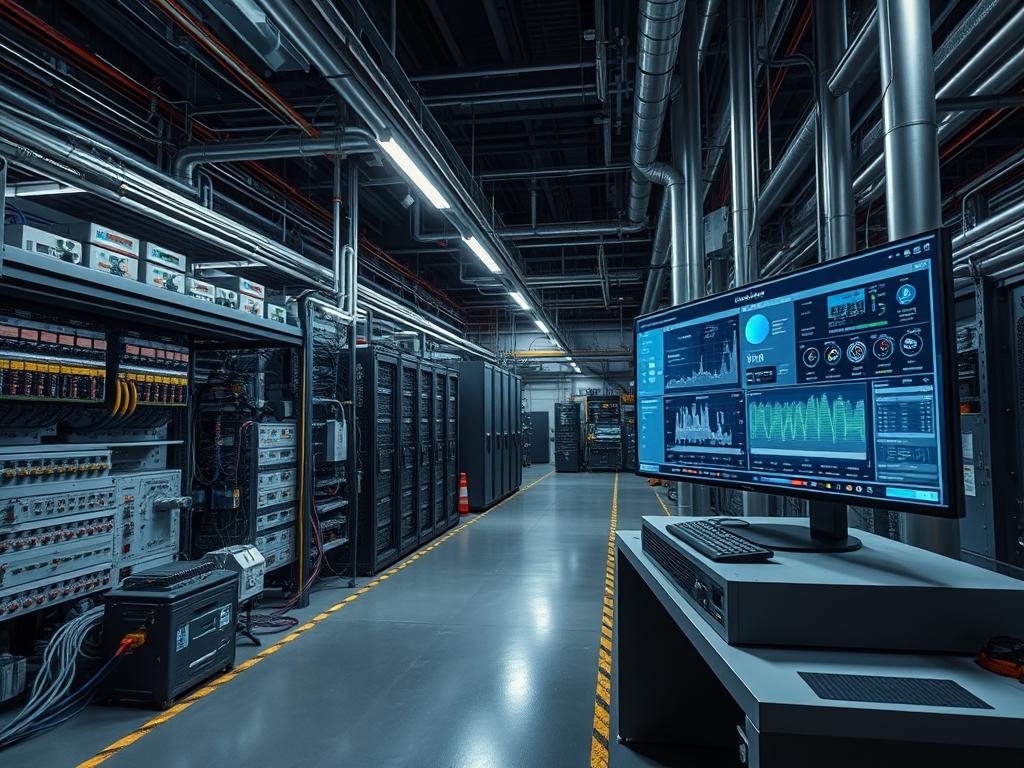
Temperature Derating Curves quantify the inverse relationship between ambient operating temperature and the maximum sustainable load an electrical or silicon-based component can handle without failure. In power electronics, these curves dictate the reduction in available wattage as the environment exceeds a specified baseline, often 40C or 50C, to prevent the thermal destruction of internal insulators and semiconductor junctions. Within high-density compute environments, derating curves provide the mathematical foundation for Dynamic Voltage and Frequency Scaling (DVFS) and thermal throttling mechanisms. When a system reaches its thermal design power (TDP) limit, the hardware abstraction layer (HAL) references these curves to adjust clock speeds or duty cycles, directly impacting throughput and transaction latency. Integrating these curves into infrastructure monitoring allow for more accurate capacity planning in environments with variable cooling efficiency, such as edge deployments or non-conditioned warehouse spaces. Failure to account for derating results in unexpected hardware shutdowns, accelerated component aging due to thermal stress, and unpredictable performance degradation under peak load conditions. Proper implementation requires cross-referencing power supply capability with processor thermal states and rack-level airflow cooling capacity.
| Parameter | Value |
| :— | :— |
| Standard Reference | IEC 60068-2, MIL-STD-810H |
| Typical Baseline Temperature | 25C to 40C |
| Derating Slope Range | 1 percent to 5 percent per degree Celsius |
| Critical Junction Temperature (Tj Max) | 100C to 105C (Silicon), 125C (Inductors) |
| Communication Protocols | SNMPv3, Modbus TCP, IPMI 2.0, SMBus |
| Sensor Accuracy Requirement | +/- 0.5C within 0C to 100C range |
| Operating Voltage Tolerance | +/- 5 percent to 10 percent |
| Data Polling Interval | 1s to 10s for real-time throttling |
| Cooling Methodology | Forced Air (CFM), Liquid (L/min) |
| Security Exposure | Low (Local Management Bus), High (Unsecured SNMP) |
Environment Prerequisites
Deployment of temperature-aware load management requires high-fidelity telemetry from the hardware layer. Minimum requirements include:
- Physical Infrastructure: Discrete thermal sensors (NTC thermistors or PT100 RTDs) positioned at air intakes and exhaust vents.
- Firmware: Baseboard Management Controller (BMC) supporting IPMI or Redfish for out-of-band thermal monitoring.
- System Software: Linux kernel 5.4 or higher for advanced P-state and T-state management; lm-sensors package for user-space visibility.
- Network: Isolated management VLAN for SNMP or Modbus traffic to prevent side-channel interference or unauthorized access to environmental controls.
- Standards Compliance: Adherence to ASHRAE A1 through A4 guidelines for data center environmental envelopes.
Implementation Logic
The engineering rationale for Temperature Derating Curves centers on preventing thermal runaway and ensuring electrical stability. As ambient temperature increases, the internal resistance of conductors and the leakage current of semiconductors rise. This creates a positive feedback loop: higher heat leads to higher resistance, which generates more heat via I2R losses. The derating curve acts as a conservative operational ceiling. In power supplies, the curve usually remains flat until a “knee” point, after which output power must be reduced linearly. In compute nodes, the logic moves from passive cooling (fan speed increase) to active clock modulation. The implementation must account for thermal inertia, the delay between a change in heat generation and its manifestation at the sensor. The control system uses a proportional-integral-derivative (PID) algorithm to adjust load based on the delta between current temperature and the derating threshold, ensuring the system operates at the highest possible performance point without crossing the safe operating area (SOA).
Identifying Thermal Thresholds via IPMI
To begin, the system must query the hardware for its current thermal profile and pre-defined derating limits. Use the ipmitool utility to pull sensor data and find the upper critical (UC) and upper non-recoverable (UNR) thresholds.
“`bash
Query all thermal sensors via the BMC
ipmitool sdr type Temperature
Output example analysis:
Ambient Temp | 24 degrees C | ok
CPU1 Temp | 45 degrees C | ok
Exhaust Temp | 38 degrees C | ok
“`
The internal logic uses these values to determine when to trigger hardware interrupts. Modifying the thermald configuration on Linux allows for manual override or fine-tuning of these response curves.
System Note: Ensure the ipmi_si and ipmi_devintf kernel modules are loaded. Hardware-level derating is often hardcoded in the BIOS/UEFI; user-space tools can only add more restrictive limits, not exceed factory-defined safety parameters.
Configuring Software-Level Throttling Policies
When the sensor data indicates the temperature is approaching the derating slope, the operating system must transition to a power-saving governor. This is done by interacting with the sysfs interface for the intel_pstate or acpi-cpufreq driver.
“`bash
Set the scaling governor to powersave when approaching derating limits
echo “powersave” | tee /sys/devices/system/cpu/cpu*/cpufreq/scaling_governor
Limit the maximum frequency to 50 percent of base clock
max_freq=$(cat /sys/devices/system/cpu/cpu0/cpufreq/cpuinfo_max_freq)
limit_freq=$((max_freq / 2))
echo $limit_freq | tee /sys/devices/system/cpu/cpu*/cpufreq/scaling_max_freq
“`
This action reduces the heat generated by the CPU package, allowing the cooling system to catch up while maintaining stable, albeit reduced, throughput.
System Note: Monitor /sys/class/thermal/thermal_zone*/temp to verify the hardware correctly reports the temperature drop after frequency modulation.
Integrating Modbus RTU for Power Supply Monitoring
In industrial environments, PSU derating is monitored via Modbus to inform the Programmable Logic Controller (PLC) of available current. This prevents the tripping of circuit breakers as temperatures rise.
“`python
Example logic for reading PSU temperature via Modbus TCP
from pymodbus.client import ModbusTcpClient
client = ModbusTcpClient(‘192.168.1.50’)
Read register 40012: PSU Internal Temperature
temp_read = client.read_holding_registers(40012, 1)
actual_temp = temp_read.registers[0] / 10.0
if actual_temp > 50.0:
# Trigger derating logic: reduce load on attached DC motors
reduce_load_sequence()
client.close()
“`
System Note: Power supplies usually have a steeper derating curve than processors. At 70C, a PSU may only provide 50 percent of its rated capacity.
Dependency Fault Lines
- Sensor Drift: Over time, NTC thermistors can lose calibration, reporting temperatures lower than actual. This leads to the system operating beyond its derated limit, causing capacitor swelling or MOSFET failure. Verification requires an external Fluke thermal imager or calibrated probe.
- Airflow Impedance: Cabling obstructs internal airflow, creating localized hotspots that the primary ambient sensors cannot detect. The system may report 30C ambient while a voltage regulator module (VRM) is at 105C.
- Fan Controller Latency: A failed PWM fan controller may not respond to the PID loop fast enough. If the fan speed does not increase as the temperature approaches the derating knee, the system will hit the hard shutdown limit without a graceful performance ramp-down.
- Kernel Module Conflicts: Loading the wrong thermal driver (e.g., pcc-cpufreq instead of intel_pstate) can prevent the OS from seeing the hardware-triggered derating events, leading to a “thermal trip” where the system abruptly loses power.
- Dust Accumulation: Particulate matter on heat sinks increases thermal resistance. This shifts the derating curve, causing performance loss at temperatures where the system previously operated at full speed.
Troubleshooting Matrix
| Symptom | Fault Code / Log Message | Verification Method | Remediation |
| :— | :— | :— | :— |
| Random Frequency Drops | dmesg: “CPUx: Package temperature above threshold, cpu clock throttled” | Check turbostat output for BCLK and multiplier changes. | Verify thermal paste integrity; check for fan obstruction. |
| PSU Shutdown | SNMP Trap: PowerSupplyTempAlarm (OID .1.3.6.1.4.1.x) | Inspect IPMI SEL for “Power Supply Failure (Critical Temp)”. | Reduce current load; improve intake airflow. |
| Network Latency Spikes | syslog: “Thermal throttling on mpt3sas adapter” | Monitor throughput vs. ASIC temperature via ethtool -S. | Install active cooling on HBA/NIC heatsink. |
| Daemon Failure | systemctl status thermald: “Failed to find thermal zone” | Check /proc/acpi/thermal_zone/ availability. | Ensure ACPI modules are loaded in kernel config. |
| Modbus Timeout | TimeoutError: “No response from unit 1” | Validate physical RS485 wiring or network connectivity to gateway. | Check for electromagnetic interference (EMI) near sensor cables. |
Performance Optimization
To maximize throughput despite Temperature Derating Curves, systems should implement proactive cooling. Tuning the fan curve to start ramping up 5 degrees before the derating knee point prevents the system from ever hitting the steep part of the curve. Utilizing cgroups to prioritize critical workloads during a thermal event ensures that low-priority services are throttled first, maintaining service level agreements (SLAs) for primary applications.
Security Hardening
Thermal management interfaces, particularly IPMI and SNMP, must be isolated. A malicious actor with access to thermal thresholds could set the derating limit to a very low value, effectively performing a Denial of Service (DoS) by forcing the CPUs into the lowest possible power state. Disable SNMPv1/2 and use SNMPv3 with AES encryption. Ensure the BMC is behind a firewall with strict IP access control lists (ACLs).
Scaling Strategy
When scaling horizontally, the derating curves of individual nodes must be aggregated into the load balancer logic. A node in a hotter part of the rack (e.g., the top units) will derate sooner than those at the bottom. The load balancer should utilize SNMP data to shift traffic away from nodes where the ambient temperature is within 10 percent of the derating knee, preserving the longevity of the hardware and maintaining consistent global latency.
Admin Desk
How can I determine the exact knee point of my server’s derating curve?
Review the manufacturer’s engineering specification sheet. If unavailable, use a load generator while slowly increasing ambient temperature in a controlled environment until dmesg reports the first thermal throttling event.
Will derating curves affect my SSD performance?
Yes. NVMe controllers have aggressive derating curves. When the controller reaches 70C to 80C, it will throttle NAND write speeds to prevent data corruption, often resulting in a 50 percent drop in IOPS.
Does liquid cooling eliminate the need for derating curves?
No, it merely shifts the curve. While liquid is more efficient, the system still has a maximum heat rejection capacity. If the coolant temperature rises, the same derating principles apply to protect the cold plate components.
Can I disable hardware throttling to maintain performance?
Disabling thermal protection is highly discouraged. Doing so overrides the derating logic and will likely lead to permanent hardware damage, such as delamination of the PCB or transistor breakdown within seconds of exceeding Tj Max.
Why does my system throttle even when fans are at 100 percent?
This indicates the ambient air temperature exceeds the cooling system’s delta-T capacity. Even at maximum airflow, the air cannot pull heat away fast enough, forcing the hardware to derate via clock reduction.